Test cases
Three different demonstration cases are included as standard with AMPLE: elastic compaction under self weight, a large deformation elastic beam analysis and elasto-plastic collapse of a body. Each of the problems are designed to demonstrate a different aspect of AMPLE as described below.
Convergence: compaction under self weight
The first example is an elastic column compressed under its own weight. Initially the column has a height of m and a width linked to the size of the background grid used to analyse the problem such that there was always one element in the horizontal direction. A plane strain assumption is set in the third direction. The base of the column is restrained vertically and both sides of the column are restrained in the horizontal direction. The column has a Young’s modulus of 1MPa and Poisson’s ratio of 0 and a density of kg/m. A body force of N/m is applied in the vertical (, ) direction over 20 equal loadsteps.
The basic setup information for this analysis, as contained on lines 57 through 67 of setupGrid, is shown below. The figure shows the setup information for an analysis with 64 elements in the -direction (nelsy) and a single element in the -direction (nelsx). The physical body is discretised by generalised interpolation material points (mpType=2), with linear-elastic material behaviour (cmType=1).
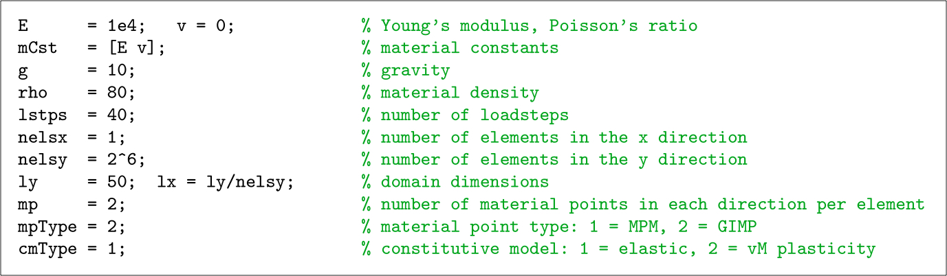
The analytical solution for the vertical Cauchy stress is
where is the gravitational acceleration (taken to be 10m/s), is the initial height of the column and is the initial vertical position within the column. If Poisson’s ratio is zero the stresses in the horizontal directions are equal to zero when the behaviour is elastic.
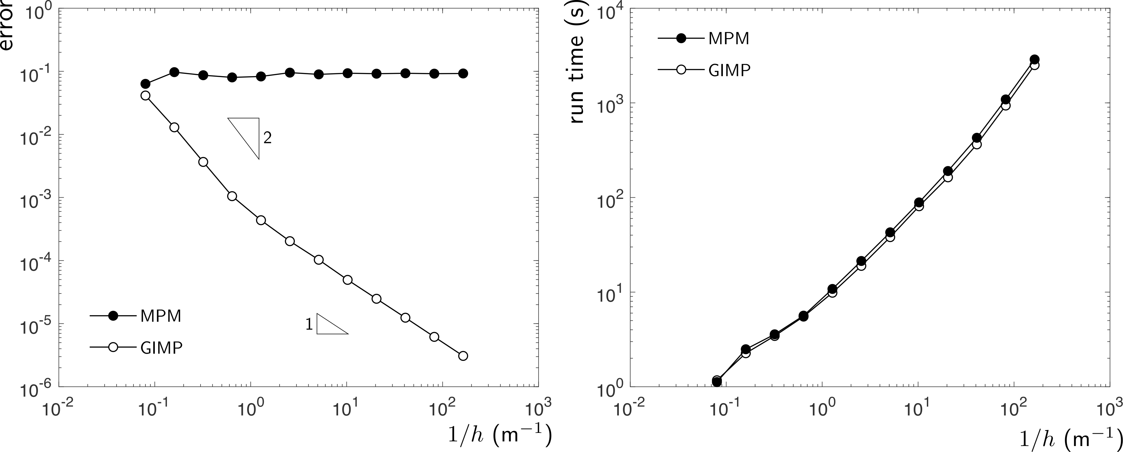
The below figure shows the convergence of the standard and generalised interpolation material point methods with background mesh and material point refinement. It is clear that the standard material point method does not converge due to cell crossing errors whereas the generalised interpolation material point method converges at an approximately linear rate. The figure also shows AMPLE’s run time with progressive background mesh refinement. For most of the analyses, the run time scales approximately linearly with the number of material points. However, when the number of elements in the -direction exceeds the time spent in the linear solver starts to dominate, with a corresponding increase in the gradient of the run time.
Visualisation: large deformation elastic beam
To run this demonstration case you will need to change line 03 of ample.m to
[lstps,g,mpData,mesh] = setupGrid_beam;
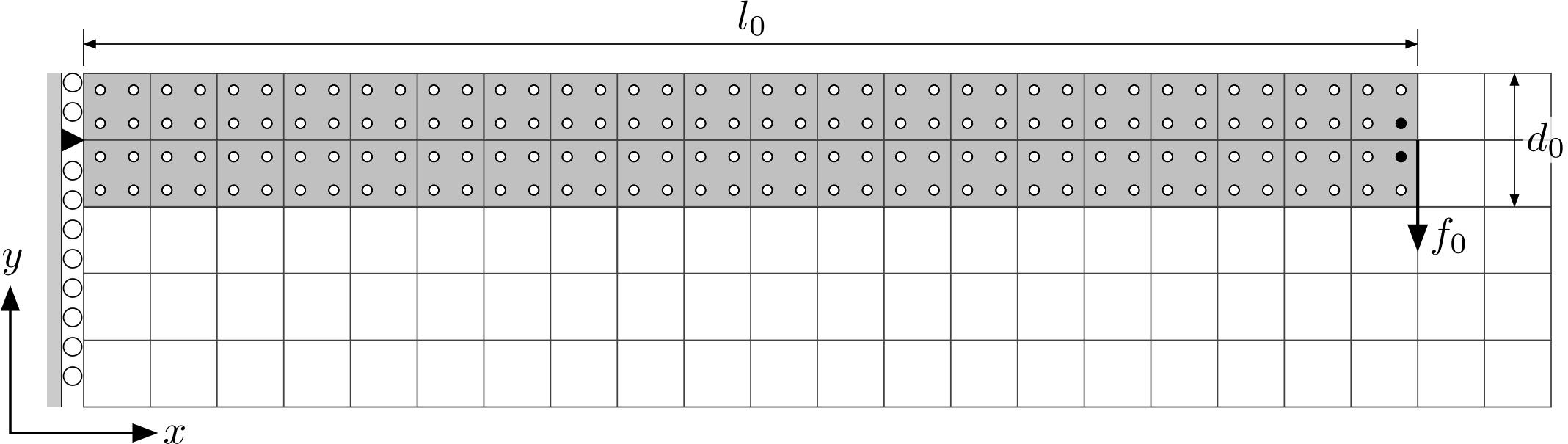
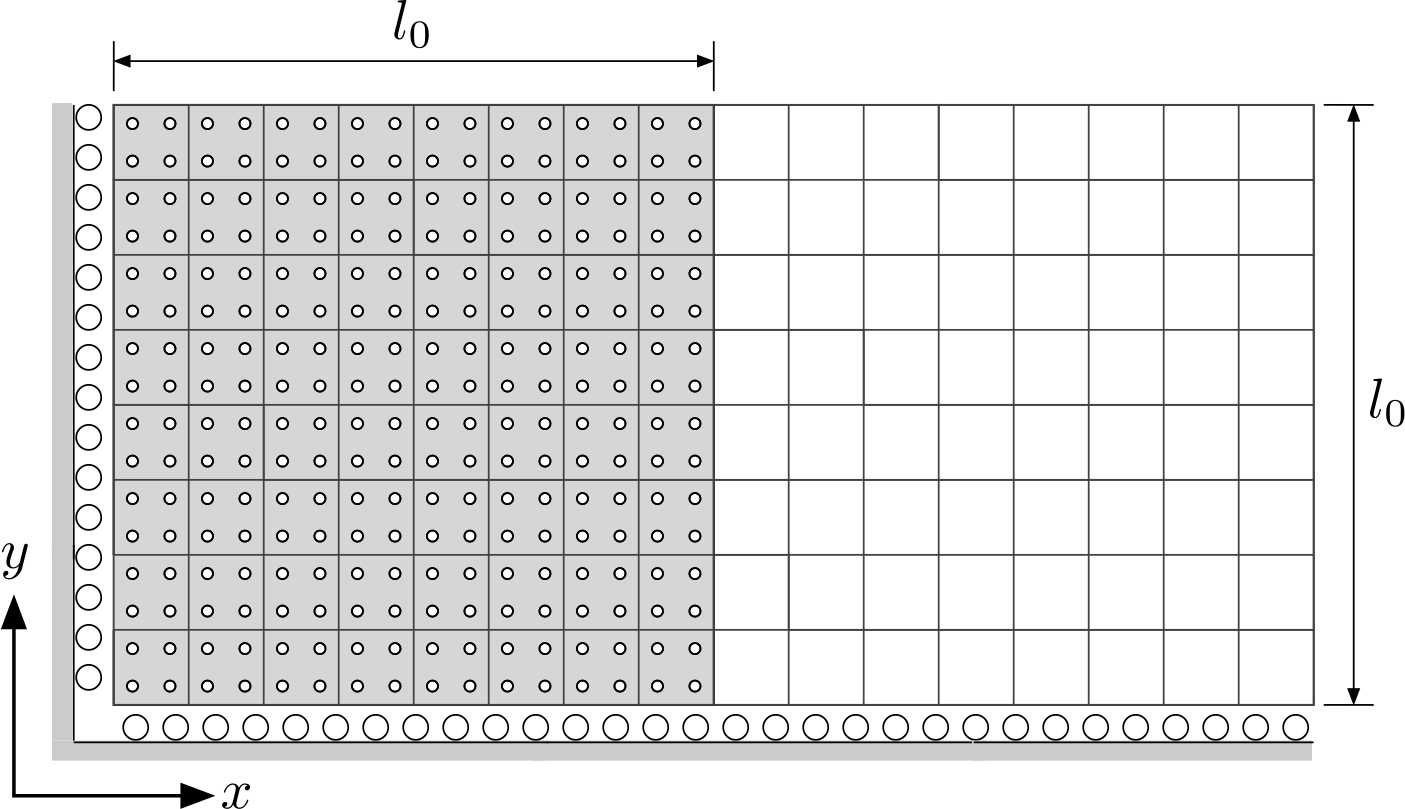
The second demonstration case is a plane strain analysis of an elastic beam subjected to a vertical end load of kN applied over 50 equal loadsteps. The beam had an initial length m and depth m and the material has a Young’s modulus of MPa and a Poisson’s ratio of . The geometry and boundary conditions with m and material points per initially active background elements are shown below. The force is split across the two material points closest to the neutral axis at the end of the beam (the black-filled circles). The neutral axis of the beam is pinned at its left hand edge and roller boundary conditions are imposed on the other background grid nodes at the root of the beam, as shown below.
In AMPLE it is suggested that users use the included scripts to generate VTK files and visualise the deformation of the material points using a VTK view (such as VisIt or ParaView). The VTK files are generated by the following two functions:
makeVtkOutputFile.m                 % generates the background mesh
makeVtkOutputMaterialPoint.m        % generates the material points
The normalised global force versus displacement response for two different background mesh sizes with generalised interpolation material points (mpType=2) per initially populated background grid cell are shown below. The analytical solution, as detailed in the thesis of [1], is shown by the discrete points. The global response of both analyses show good agreement with the analytical solution.
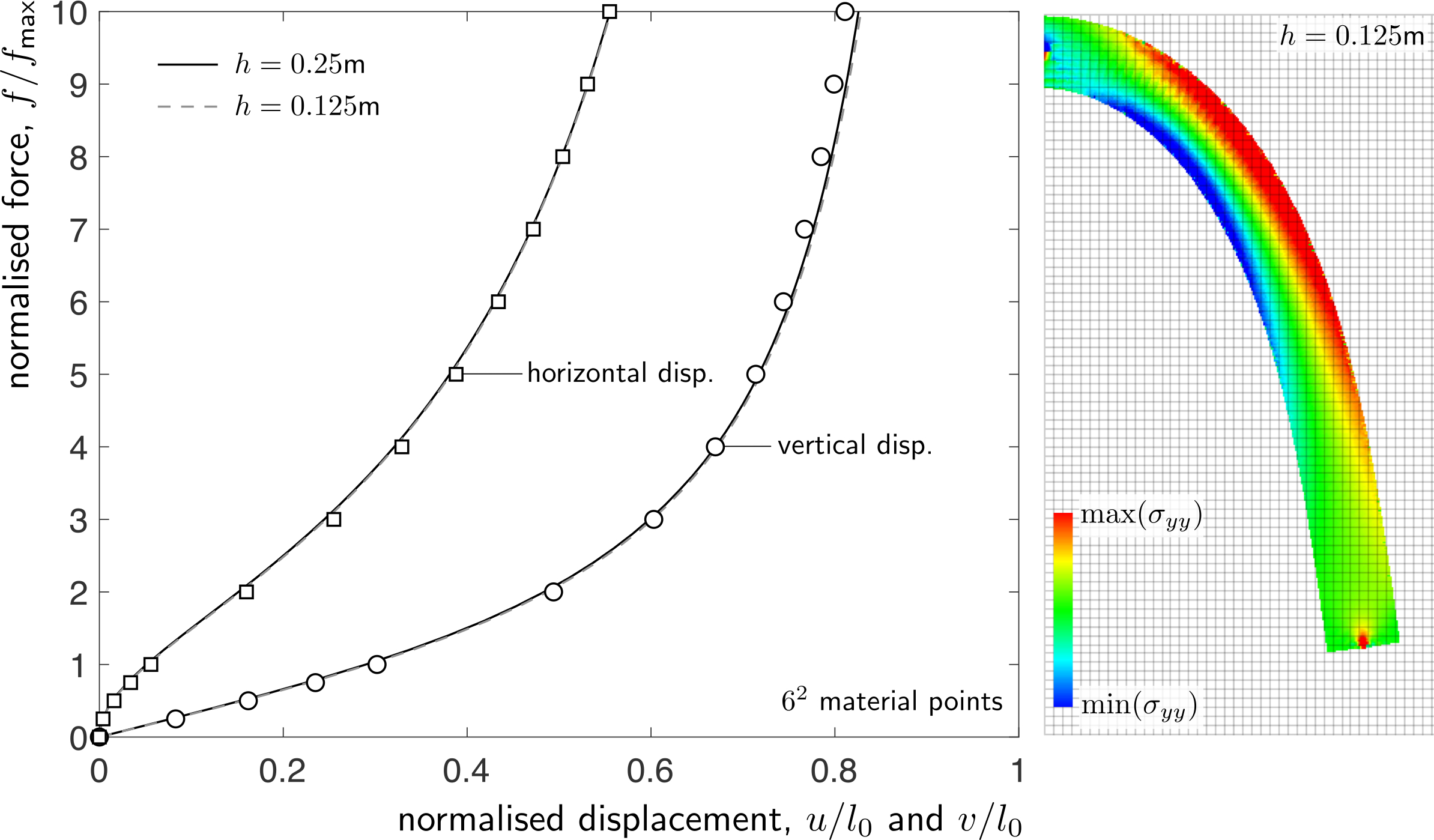
The above figure also shows the deformed material point positions at the end of the m analysis that have been coloured according to the normal stress in the -direction, . The figure was produced from the VTK output files that are generated on line 32 of the main ample.m script via postPro.m and saved into the output folder
Material model: elasto-plastic collapse
To run this demonstration case you will need to change line 03 of ample.m to
[lstps,g,mpData,mesh] = setupGrid_collapse;
The final demonstration example is the elasto-plastic collapse of a rectangular body of material subject to a gravitational body force. Due to symmetry only half of the body is modelled and the initial discretisation of the problem is shown in below with m, m and material points per initially filled background cell (the grey-shaded region). Roller boundary conditions are imposed on the base and the left hand edge of the background mesh. The material is modelled using a linear-elastic, perfectly-plastic von Mises constitutive formulation.
For this analysis, the yield strength of the material is kPa, the Young’s modulus is MPa and Poisson’s ratio is . A body force of kN/m (density of kg/m and gravitational acceleration of m/s) is applied over 40 equal loadsteps.
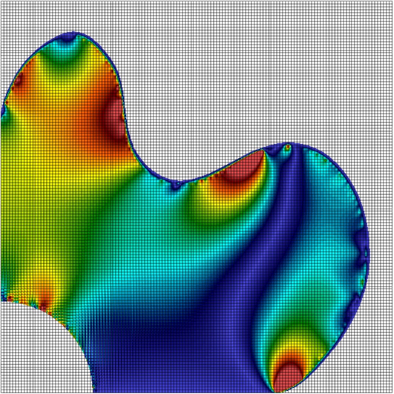
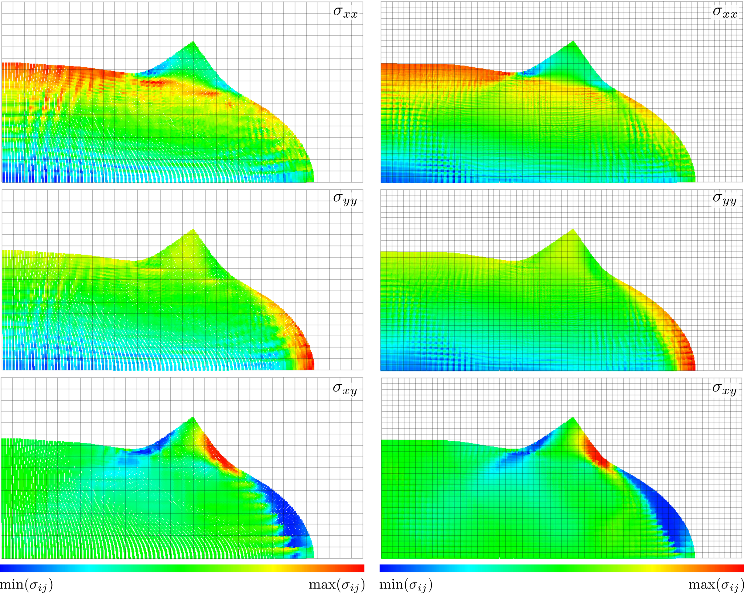
The deformed material point positions at the end of the analysis for m and m with material points per initially populated background grid cell are shown below. The material points are coloured according to , and , where the blue and red regions show areas of low and high stress, respectively. There is very little deformation for the first 20 loadsteps (up to kN/m) but beyond this value the material rapidly collapses and achieves the final deformed state shown below.
[1] T. Molstad, Finite deformation analysis using the finite element method, Ph.D. thesis, University of British Columbia, 1977.